Design the circuit
Define electrical behavior, components, pads, and interconnects with familiar engineering logic.
SoCl connects electronic design, embroidery-ready fabrication, and physical testing in one textile-native manufacturing platform.
Conventional tools define the circuit, but they do not carry that design cleanly into stitched geometry, conductive thread paths, and fabric-compatible structures.
Define electrical behavior, components, pads, and interconnects with familiar engineering logic.
Convert rigid-board assumptions into flexible geometry that respects textile and stitch constraints.
Generate embroidery-ready paths without rebuilding the design manually in a separate workflow.
Move from circuit geometry to embroidered fabrication, verification, and ECG-ready textile hardware without losing design intent.
Create electronic-circuit layouts and textile component.
Convert the design into stitch paths and embroidery-machine instructions for cloth fabrication.
Evaluate electrical, material, fabrication, and functional behavior in real time using the measurement method appropriate to each component or system.
Realize electronic structures directly on flexible fabric for comfortable wearable integration.
Deploy the finished e-textile in ECG and other biomedical sensing applications.
Build circuits, components, routing, pads, electrodes, and textile-aware geometries.
Represent the distinct properties and measured responses of threads, structures, and electronic elements.
Translate design intent into stitch paths, process logic, and embroidery-compatible output.
Design data, fabrication and functional results remain connected throughout the process.
Observe and evaluate the relevant electrical, physical, fabrication, and system-level behavior for each design.
Test complete structures as working electronics on flexible, wearable, and conformal fabric surfaces.
Connect validated fabric electronics to biomedical, sensing, wearable, robotic, IoT, and emerging applications.
Design • fabricate • validate • deploy
The next generation of electronics will be built into products.
Our vision is a manufacturing ecosystem where textile surfaces are designed, fabricated, and measured as complete electronic systems.
The platform separates measured foundations, published results, current capabilities, and active research directions.
Explore application modules, sensing structures, wearable interfaces, and fabrication-oriented research prototypes.
Design data, component behavior, fabrication output, authentication, and validation workflows remain connected through the platform backend.
Connect with the SoCl team for prototype development, platform integration, research partnerships, and manufacturing strategy.
A clear technical reference linking electrical equations, textile geometry, fabrication constraints, and the SoCl design workflow.
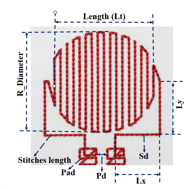
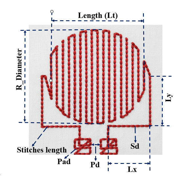
An embroidered resistor is created by stitching a long conductive-thread path on cloth. The resistance is mainly controlled by the thread linear resistance and total stitched length. A meander shape is useful because it fits a long thread path into a compact textile area.
For SoCl, the parameter named rho should be interpreted as linear thread resistance, RL, in Ω/m. It is not bulk resistivity. The target resistance is converted into the total stitched length needed for the embroidered path.
total_length_mm = (R_target / R_L) * 1000. Enter target resistance or path length in the shared EDA dialog. The meander uses a single circular radius (equal X/Y diameter) and is sized from its centreline length, including leads; terminal fill is excluded from the series-length estimate. The two 1210 connection pads remain 2.50 × 2.50 mm with 4.00 mm centre spacing.
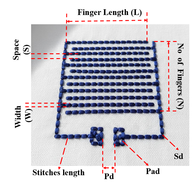
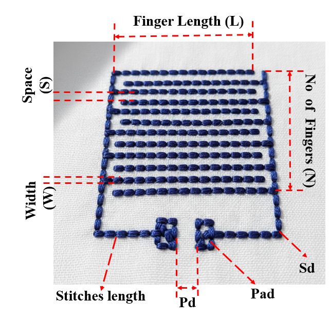
An embroidered capacitor can be made as an interdigitated planar structure. Neighboring conductive fingers act as electrodes, and the textile/substrate region between them behaves as the dielectric path.
Enter a target capacitance in pF in the EDA tool. SoCl calculates the finger count and length for the same IDC pattern using the existing first-order estimate. Manual finger-count and length entry is also available.
L = C_target / [0.008854187817 × εr × ((2w + s) / s) × (N − 1)]. SoCl searches integer finger counts while retaining the IDC comb pattern and side terminals, with a minimum 20 mm finger length. Direct entry accepts pF or nF through 1.4 nF (1,400 pF). Larger layouts can expand the drawing area; this does not change the physical machine hoop size. Connection pads stay at 2.50 × 2.50 mm with 4.00 mm centre spacing (1.50 mm edge gap), independent of the capacitance. Defaults: w = 0.40 mm, s = 0.70 mm, εr = 1.5. This is the existing layout estimate, not a calibrated IDC field model; verify the fabricated capacitance by measurement.
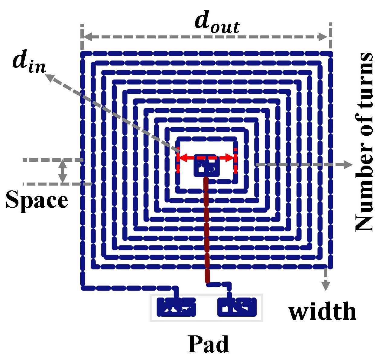
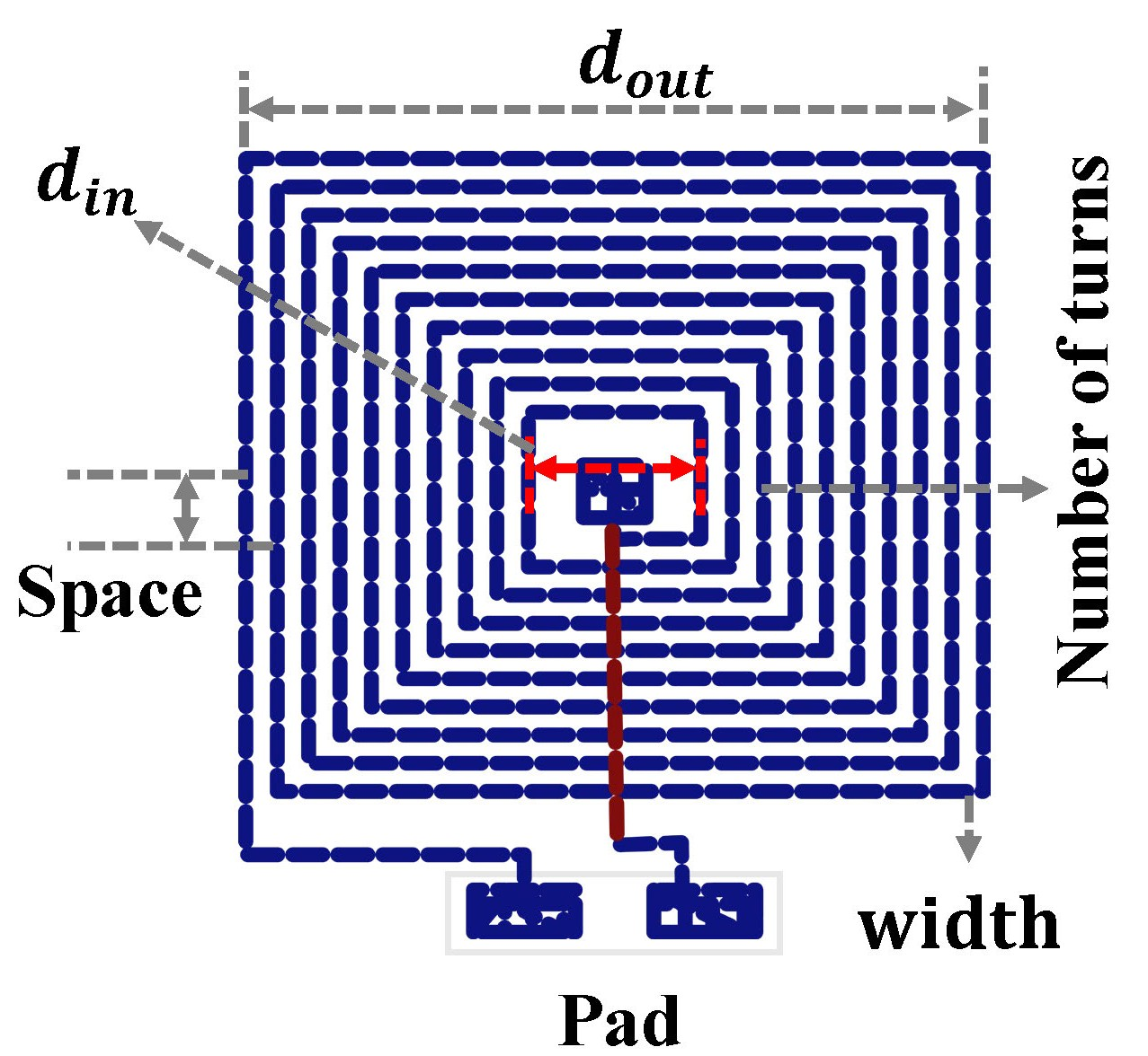
An embroidered inductor is modeled as a planar square spiral. The turn count, average diameter, trace width, and spacing control the magnetic field path and therefore the inductance.
The square-spiral inductor uses a modified Wheeler-style approximation. The important unit check is that davg must be converted from millimeters to meters before calculating inductance in henries.
d_avg_m = d_avg_mm / 1000, calculate L_henries, then display L_nH = L_henries * 1e9. Enter target inductance in nH or specify turns and inner diameter in the shared EDA dialog. The 1210 connection pads remain 2.50 × 2.50 mm with 4.00 mm centre spacing. The centre pad requires an insulated jumper to terminal 2; it is shown as a dashed guide and is not stitched across the spiral.
Compare representative conductive threads used for textile routing, electrodes, passive components, and smart-textile prototypes.
Explore published systems, prototype directions, and design tools for sensing, health, wireless interaction, and fabric-integrated computing.
Each example links to its publication or open-source research repository.
Embroidered electrode structures for configurable biopotential signal acquisition and textile-integrated sensing research.
Textile-integrated electrode concepts for cardiac and muscle-signal monitoring within wearable systems.
Embroidered sensing structures and cloud-manufacturing workflows for pressure, deformation, and human-motion applications.
These concepts are at different stages of design, fabrication, and experimental maturity.
Textile electrochemical sensing concepts for monitoring biomarkers during physical activity.
Embroidered antenna structures for passive identification, wireless interaction, and textile-integrated communication.
Garment-integrated electrode concepts for controlled TENS and EMS delivery research.
Soft capacitive interfaces designed for integration into garments and responsive fabric surfaces.
Textile sensing concepts for localized thermal and body-temperature monitoring.
Design embroidered transistor cells and AND, OR, and NOT logic-gate layouts for active textile-electronics research.
Bring a component, sensor, circuit, or manufacturing question to the SoCl team.
Work with the SoCl and UVA WEARLab team on design review, research partnerships, and manufacturing strategy.
Review the application, material system, embroidery workflow, and engineering requirements.
Start a design reviewCollaborate on embroidered sensing, biopotential interfaces, soft circuits, active devices, or digital textile manufacturing.
Discuss researchPlan around conductive materials, machine constraints, DST workflows, repeatability, and scale-up.
Discuss manufacturingPrincipal Investigator
Associate Professor, Mechanical and Aerospace Engineering Department and Electrical and Computer Engineering
University of Virginia
Grad : Researcher
Mechanical and Aerospace Engineering
University of Virginia